VR Teleoperation Stack for Robot Manipulation
Building a VR teleoperation stack for robot manipulation, from inverse kinematics to the operator experience.
The leader and follower arm setup is a standard teleoperation method for robotic manipulation. The follower is the robot being controlled, which mirrors the motion of the leader, a copy with the same kinematic structure that the operator moves by hand. This system is reliable and intuitive, but each leader is specific to a single robot configuration and the hardware can get quite expensive. GELLO is a low cost system using weak motors in the leader arms purely to read out joint angles. Because those motors are too weak to drive the leader to the follower’s pose, you can’t cleanly take over mid-rollout to collect intervention data. The follower would otherwise jump to the leader’s current pose. A VR headset with controllers sidesteps these issues: a single headset can be used across robot configurations, and you can use it to collect intervention data too.
In this post I’ll explain how I built a VR teleoperation stack for robot manipulation1: the inverse kinematics that makes the arm intuitive to control, the safety features that keep it well-behaved, and the camera and haptic feedback that close the loop. The full stack is open source, so you can adapt it to your own arm and skip physical leader arms entirely.
Overview
The robot arms I’m working with are two 6-degree-of-freedom (DoF) TRLC-DK1 arms each with a 1-DoF gripper from The Robot Learning Company, and the VR headset I’m integrating is the Meta Quest 3. The following is applicable to any robot arm and VR headset though.
The stack spans three places (figure 1): the headset, a workstation, and the robot. The operator moves the controllers, a web app on the headset reads their pose and streams it to the workstation, where a relay hands it to the inverse-kinematics (IK) solver that converts it into the robot’s joint angles. Haptic feedback travels back the same way, so the operator can feel what the robot is doing.
For my safety and the safety of the robot I iterated on the design using a MuJoCo simulation model of the arm. This allowed me to aggressively stress-test my implementation before deployment.
Here is how the finished stack looks for classic teleoperation (figure 2) or human-in-the-loop intervention during a policy rollout (figure 3).
Inverse Kinematics: From Pose to Joint Angles
Controlling robot arms with leader arms is straightforward. You just read out the joint angles from the leader arms and set them on the robot’s joints. With a controller in your hands you don’t get the joint angles directly. What you demonstrate instead is the position and orientation you want the robot’s gripper to be in. We need an inverse-kinematics solver for this, which calculates the joint angles from the target pose of the gripper. Once the solver produces the joint angles, they can be fed directly into the existing scripts that drive the robot.
The hard part isn’t solving the equations, it’s making the solution feel intuitive for the operator. A couple of ideas were needed to get there.
Control that feels natural
The standard approach to such an IK problem is damped least squares (DLS), also called ridge regression: you minimise the squared error between the target pose and the current pose of the robot’s gripper, plus a regularising penalty that prevents extreme joint changes. This tracks the pose, but it doesn’t feel natural. If I rotate my hand without moving my wrist, I’d intuitively expect only the end of the robot to move. Instead the whole arm swings (figure 4, left). This happens because you solve for the end-effector, a point all the way at the front of the gripper. A pure rotation of your hand keeps that point still, and all the joints of the robot arm are free to move to achieve the orientation.
The fix is to stop solving for the end-effector pose with all six joints at once. I split the joints into two groups: the first three track the position of a point at the wrist (not affected by the other joints), and the last three track the orientation. I solve them sequentially with DLS, starting with the position. This way a pure rotation of your hand keeps the robot’s wrist still (figure 4, right), which captures the operator’s intention far better.
Details
The naive solver takes one DLS step on the full 6-D pose error each tick:
with the six joint angles, the Jacobian and a damping coefficient. Decoupling replaces it with two smaller DLS steps. The position half moves joints 1-3 to track the wrist point, using their Jacobian and the 3-D position error :
Then, with joints 1-3 moved, the orientation half takes the same step on the wrist joints, with the remaining orientation error as a rotation vector and the rotational Jacobian:
Both halves are the same equation with their own Jacobian and error. I read the forward kinematics and Jacobians from the robot’s URDF loaded into MuJoCo (the same model I simulate with), and warm-start each solve from the previous tick’s angles.
Symbols:
- the position Jacobian of joints 1-3 at the wrist point.
- the 3-D position error of the wrist point.
- the rotational Jacobian of joints 4-6 at the end-effector.
- the 3-D orientation error of the end-effector, as a rotation vector.
- the damping coefficient.
Staying stable near singularities
The damping coefficient in the DLS solution helps prevent enormous joint motion at badly conditioned configurations (singularities) of the robot arm. These occur when two joint axes coincide, or when you fully extend the arm and reach the end of the reachable workspace. In both cases the robot arm loses a degree of freedom, and small target changes can then lead to very large joint-angle changes. The damping trades some tracking accuracy for stability, but a constant coefficient across all configurations is hard to tune well: the damping should have its biggest effect at singularities, while everywhere else you want responsive tracking, not sluggish motion.
So I let the damping adapt: near zero where the arm is far from a singularity and rising as it comes close.
Details
A manipulability measure falls to zero at a singularity. I turn it into a ramp that is in normal poses and rises to at the singularity, then use it to blend a baseline damping with extra damping:
This is what enters the DLS equations above. Each half computes its own: for joints 1-3, shrinks near full extension; for the wrist, works out to exactly on this robot, shrinking as joints 4 and 6 line up at gimbal lock.
Symbols:
- the manipulability of the sub-problem’s joints.
- the manipulability threshold below which damping starts ramping in.
- the ramp factor: while (normal poses), rising to as (at the singularity).
- the baseline damping that’s always present.
- the extra damping added only near the singularity.
Elbow folding
Damping bounds how fast the arm moves through the fully-extended singularity, but it says nothing about which way to go once it is there. Coming back out of full extension, the elbow can fold up or down (figure 5, left).
I settle it with a gentle pull toward a default arm pose, one where the elbow is already folded the right way. The pull is weak enough that I never feel it in normal use, but right at the singularity, where the solver is otherwise indifferent, it is enough to tip the elbow the correct way (figure 5, right).
Details
The pull is a spring in joint space toward a rest pose , added as one extra term to each side of the position step:
Symbols:
- the stiffness of the joint-space spring.
- the default arm pose the spring pulls toward.
- the current joint angles.
A last line of defence
Everything so far shapes the IK solver. I wanted one more safety feature on top: a hard ceiling on the velocity of every joint, no matter what the solver asks for. A very simple but effective safeguard. Better safe than sorry!
Reading the Controller: From Hand to Target Pose
The IK solver needs a target pose to track. Producing a good one from the VR controller is a problem of its own. The controller reports a raw position and orientation in the headset’s own world frame, but feeding that to the IK solver directly doesn’t quite work. The core idea is to use relative motion as the target rather than the absolute pose, and then fix a few things along the way.
Moving with a clutch
The main reason I don’t map the controller’s absolute pose to the robot is that I would have to start each session with my hand in exactly the robot’s pose, otherwise the arm jumps. That is the same problem passive leader arms have during interventions.
Instead I map the change in pose while I hold a button, the clutch. On the press I capture the controller pose and the gripper pose at that instant, and while the button is held, the gripper follows the controller’s movement since then. On release the target freezes, so I can reposition, and grab again to carry on (figure 6). This is similar to lifting a mouse off the desk and setting it back down.
I additionally have a parameter to scale this relative motion. This one is like the speed setting you can adjust for your computer mouse. I like to keep it around 1.5.
Details
On the rising edge I capture the engage frame: the controller pose and the current end-effector pose . While the button is held, the target is the engaged end-effector pose moved by the controller’s delta since engage:
The translation delta is scaled by a gain and rotated from the headset frame into the arm base by . The rotation delta is the controller’s rotation since engage, conjugated by into the arm base.
I simplified the position update here. As explained in the IK chapter, the robot tracks position at a point on its wrist rather than at the end-effector, so the position target also has to account for the shift a wrist rotation induces; I leave that term out to keep the equation readable. The implementation also accumulates these deltas incrementally each frame rather than recomputing them from the engage frame, which is what lets the next section keep the target within reach.
Symbols:
- the current controller position and orientation.
- the controller pose captured at engage.
- the end-effector pose captured at engage.
- (as a quaternion ) the rotation from headset world into the arm base.
- the translation gain ( = 1:1 motion).
Keeping the target reachable
So far the mapping trusts the target completely. But the robot has joint limits and a finite reach, and nothing stops me from giving a target far ahead of what the joints can actually do. That stored-up overshoot causes trouble. If I push joint 6 more than past its limit, for instance, the same orientation can be reached by turning the other way, and the joint flips around even though that was never my intention (figure 7).
I fixed this by treating the target like a mouse cursor at the edge of the screen again: the cursor stops at the edge no matter how far you keep sliding, the extra motion is thrown away, and when you slide back it follows along. The target pose works the same way. It may run at most a fixed distance or angle ahead of where the robot actually is, and anything beyond that is absorbed.
The price is that absorbed motion is lost, so my hand and the robot can slowly fall out of alignment within one grab. In practice it doesn’t matter: you rarely hit these edge cases, and releasing the clutch and grabbing again realigns them.
Twisting without drifting
We now come back to a side effect of decoupling position from orientation in the IK. The robot tracks its position at a point on its wrist, so I need to read out my position at my wrist too. But the controller reports its position at the grip, roughly the middle of the controller. When I rotate my hand, this point swings through an arc, the system reads that arc as a change in position, and the robot’s wrist drifts. Figure 8 on the left shows this effect and visualises a blue sphere at the grip, where the controller reports its position.
The fix is to read the pose not at the grip but at the wrist pivot, a fixed offset from the grip. I find that offset with a short calibration: I hold my wrist roughly in place and only twist it for a few seconds (figure 9), and solve for the offset that keeps the read-out point as still as possible. From then on the read-out sits at the wrist pivot, and pure twists produce almost no translation. In figure 8 on the right you can see the calibrated location of the blue sphere where the position is read out.
Details
The wrist pivot is a fixed offset from the grip in the controller’s own frame. Each calibration frame gives a grip position and controller rotation , and the shifted point should stay constant if is the true pivot. I solve for the that keeps it as constant as possible, a small linear least-squares problem:
with and mean-centered over the samples. From then on the read-out point is shifted to .
Symbols:
- the grip position and controller orientation of sample .
- the offset from grip to wrist pivot, in the controller’s frame.
- the sample means of position and orientation.
Keeping forward aligned
There is one last thing I found convenient. The rotation that maps my hand’s motion into the robot’s frame is calibrated once, by aligning the headset’s axes with the robot base. But I don’t always stand facing the robot the same way, and with a fixed mapping “my forward” then points off to the side (figure 10, left). I instead measure my heading at the moment I engage the clutch and fold it into the mapping, so “forward for me” stays “forward for the robot” wherever I stand (figure 10, right).
Details
The mapping rotation starts from a fixed calibration . At each engage I measure my current heading , the rotation of the headset about the vertical axis, and subtract it:
is the used for that grab.
Symbols:
- the fixed rotation from headset world into the arm base.
- the operator’s heading at the moment of engage.
- a rotation about the vertical (world-up) axis.
Transport: From Headset to Workstation
Now for the transport of the controller poses from the VR headset to the workstation. The headset runs a small web page built with WebXR, the browser standard for VR that gives a web page access to the headset and controllers. The page reads the controller poses and streams them over a WebSocket, a persistent two-way connection that keeps a low-latency channel open to the workstation. On the workstation a relay receives them and the teleoperation driver subscribes to it. I set up two ways to connect the headset and the workstation: over a cable or over the network.
In this table you can see the round-trip latency I measured for both connections:
| Connection | median (p50) | mean | p95 | max |
|---|---|---|---|---|
| Cable (USB) | 1.6 ms | 1.8 ms | 3.5 ms | 3.8 ms |
| Network (LAN) | 7.6 ms | 32 ms | 130 ms | 144 ms |
The cable is not only faster but also far more consistent. Over the network the median is still fine, but every few samples the latency spikes above 100 ms, which can make the robot stutter. Over the network you are not restricted by a cable but I still default to the cable whenever possible. I need the headset plugged in anyway for longer sessions, so it doesn’t run out of battery.
In principle the same setup also works over the internet, which would allow for fully remote teleoperation. Instead of reaching the workstation on the local network, you expose the relay through a public tunnel (for example with cloudflared) and the headset connects to that address from anywhere. The software itself doesn’t change. But the LAN spikes above already show how much jitter a single wireless hop adds, and over the internet it only gets worse. Additionally, for real remote operation you need to stream the camera feeds back as well (more on that in the next chapter). Unlike the pose stream, the camera video is sent directly between the headset and the workstation instead of through the relay. Getting that direct link to work across the public internet needs an extra relay server for the cases where firewalls block it, which I haven’t set up, so video currently works only on the local network.
LAN
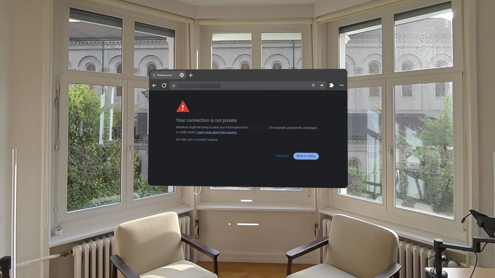
For the network connection the headset reaches the workstation over Wi-Fi. WebXR only runs in a secure context, so the server has to speak HTTPS. I generate a self-signed certificate for it, but because it isn’t signed by a trusted authority the Quest’s browser shows a security warning the first time you open the page (figure 11). You simply have to allow it anyway, and from then on the headset talks directly to the workstation’s IP address.
USB
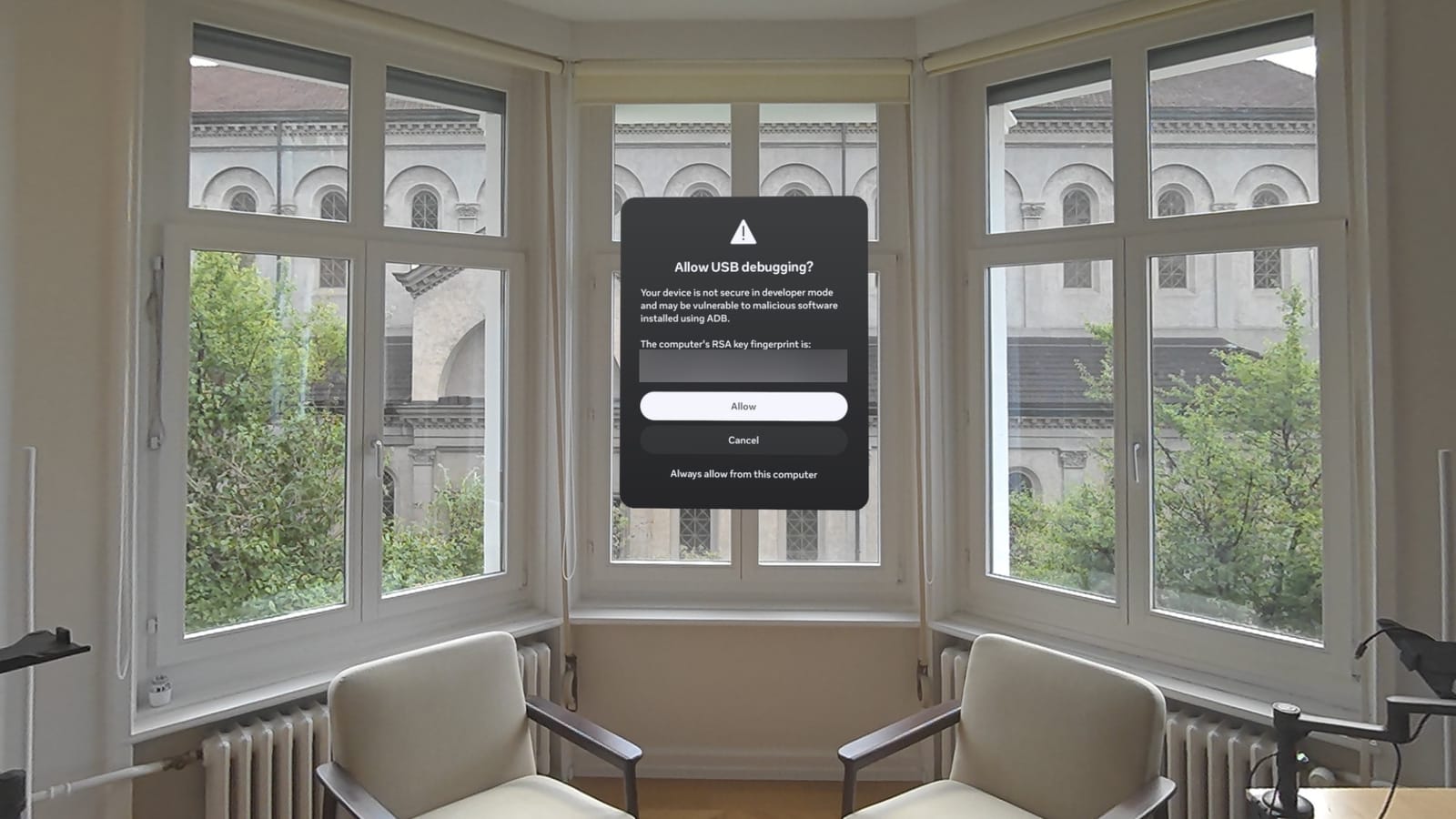
To connect over a cable you need adb (the Android Debug Bridge) on the workstation. For the headset to accept it you first have to enable developer mode on the Quest (via the Meta Horizon app), which requires a free Meta developer account. Once developer mode is on and the cable is plugged in, the Quest shows a prompt to allow USB debugging, which you accept (figure 12). With adb reverse the headset’s browser can then reach the workstation on localhost, and since WebXR treats localhost as a secure context even over plain HTTP, there is no certificate and no security warning to deal with.
The Operator Experience
Everything above makes the robot move correctly. This chapter is about what makes it pleasant to use. It comes down to a few things:
- a control panel accessed in the headset,
- a couple of features when pressing different buttons on the controller,
- the robot’s camera feeds streamed into VR,
- force feedback through the controller’s vibration,
- and a couple of comfort hacks.
The web app
The same WebXR page that streams the controller poses is also the control panel (figure 13). Besides the button to enter VR, it has a settings panel whose sliders are parameters from the previous chapters, such as the translation gain or the per-joint velocity caps, exposed as live controls that take effect immediately. Being able to retune the feel without restarting anything made finding good values much faster.
Buttons
Besides the clutch (figure 6) I added two more features available with buttons on the controller. A precision modifier that I hold to temporarily lower the translation and rotation gains for fine work (figure 14), and a button that sends the arm back to its home pose (figure 15).
Camera streams
The wrist and overhead cameras can optionally be streamed into the headset as floating panels (figure 16). This lets me teleoperate without looking at the real robot at all, which is what makes remote operation realistic and also shows you what the robot actually sees.
Haptic feedback
The gripper reports its torque, which I map to a vibration of the controller so I can feel when I have grabbed something. To avoid a buzz every time the gripper closes on nothing, the threshold for firing the haptic rises with how fast the gripper is moving, so a quick close needs more torque before it buzzes. Past the threshold the vibration ramps up with torque until it saturates.
Figure 17 shows a real grasp, with the gripper torque rising past the threshold and the resulting intensity sent to the controller.
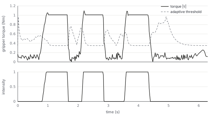
The gripper torque is not the only signal I turn into vibration. The IK solver also reports how close the arm is to “trouble”: pushing against a joint limit, dragging the target out of the reachable workspace, or coming close to a singularity. These are combined into a second vibration intensity for the matching controller, and the stronger of the two signals drives the buzz. This way I feel the limits of the robot directly in my hand instead of only noticing it visually.
Details
The threshold rises with gripper speed, and the intensity ramps linearly from the threshold up to a saturation torque:
Symbols:
- the measured gripper torque.
- the velocity-adjusted threshold above which the haptic fires.
- the base threshold ( Nm).
- the gripper velocity, how strongly the threshold reacts to it.
- the torque at which the vibration reaches full intensity.
Convenience
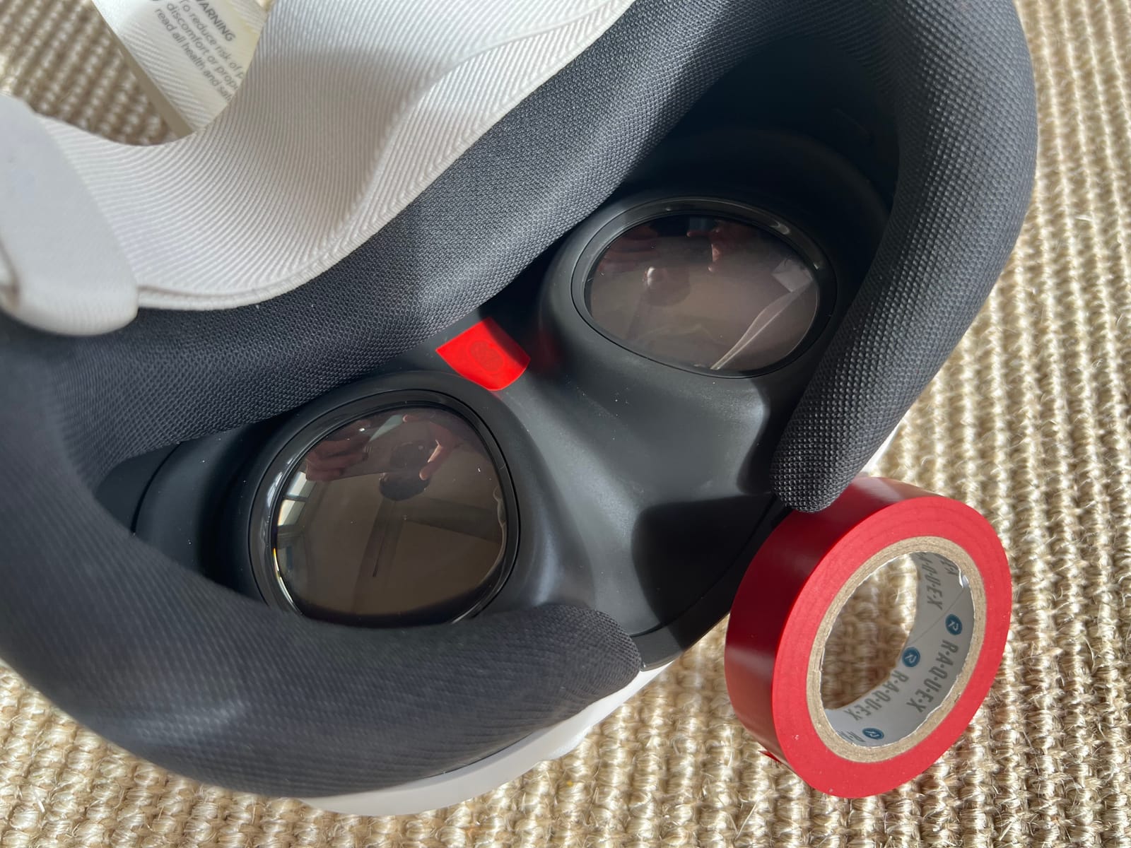
When teleoperating the robot with the Quest I find it much more comfortable to look at the robot directly and not through the headset. Since I need the headset for tracking the pose of the controllers, I just pull it all the way down to my chest (figure 18). When you take off the headset from your face, it goes to sleep quite fast. To get around this, I just put a small piece of tape over the proximity sensor (figure 19), which keeps it awake.
Closing
Most of this stack transfers directly to other setups. The transport, the controller mapping with its reach limit, and the haptics don’t care which robot is on the other end. The decoupled-IK approach carries over to any 6-DoF arm with a roughly spherical wrist, but the solver itself is written against the DK1: adapting it means describing your arm’s geometry to the solver (the gripper-mount rotation and the wrist-anchor placement, built from your URDF) in addition to retuning the rest pose and the velocity limits.
I hope this helps people integrate a VR headset themselves to teleoperate their robot arms.
All the code for this stack is open source and available on GitHub: vr-teleop-kit. The post describes the stack I built, the repo is the kit to build your own.
Footnotes
-
Work done while at Dream Machines. ↩︎